3 Phase Electrical Phasor Diagram Wiring Schematic
Assortment of phasor generator wiring diagram. Three phase power from the utilities is connected to the main breaker through three-phase energy meter.
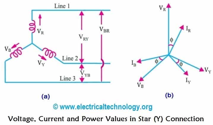 Star Connection Y 3 Phase Power Voltage Current Values
Be sure the switch is in the NORMALposition.
3 phase electrical phasor diagram wiring schematic. The three windings of the coils are connected together at points a 1 b 1 and c 1 to produce a common neutral connection for the three individual phases. Voltage and current Line to Neutral Line to Line and Phasor Diagrams. A vector diagram can be constructed based on following principles.
Y-Y Y- -Y and -. The schematic diagram at the upper right is perhaps easier to analyze as the delta connections can clearly be seen. It shows the components of the circuit as streamlined shapes and also the power as well as signal links in between the devices.
My Patreon page is at httpswwwpatreonco. Electrical 3 Phase Wiring Diagrams wiring diagram is a simplified usual pictorial representation of an electrical circuitIt shows the components of the circuit as simplified shapes and the knack and signal friends amid the devices. Three Phase Motor Connection STARDELTA Without Timer Power Control Diagrams.
A wiring diagram is a simplified conventional pictorial representation of an electric circuit. Plug this device into the Three Phase 3φ wall power source using the 3-Phase Cord Set and determine the phase sequence ABC or CBA using the PSI. The phasor diagram of the -Y connection of the three phase transformer is shown in the figure below.
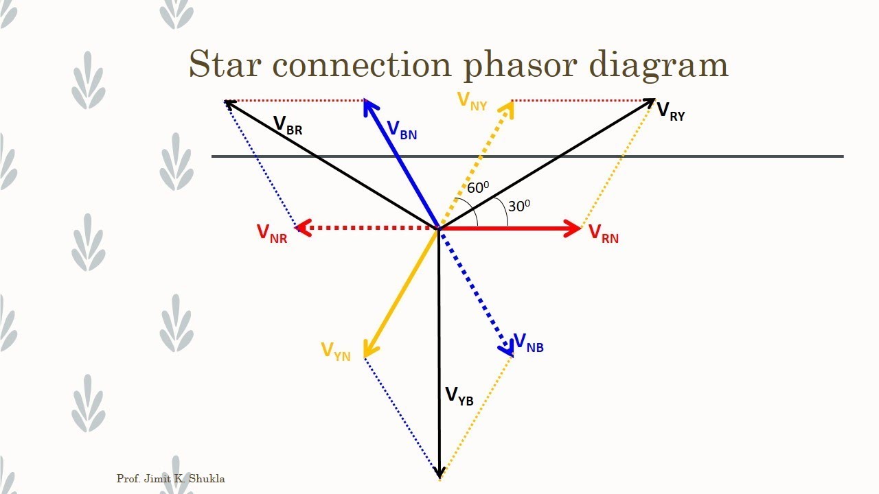
In this section well review the operating characteristics of basic delta-delta wye-wye delta-wye and wye-delta connections of the transformer. It reveals the parts of the circuit as simplified shapes and the power as well as signal links between the gadgets. Similarly V bn leads V BN by 30º and V cn leads V CN by 30ºThis connection is also called 30º connection.
Three Phase Motor Connection Schematic Power and Control Wiring Installation Diagrams. Single-Phase Electrical Wiring installation in a Multi-Story Building Three-Phase Electrical Wiring installation in a Multi-Storey Building. It is a type of polyphase system and is the most common method used by electrical grids worldwide to transfer power.
How these windings are connected together determines the configuration of the transformer delta wye etc. The shell type core has three sets of primary and secondary windings. A transformer can not act as a phase changing device and change single-phase into three-phase or three-phase into single phase.
Read Or Download The Diagram Pictures Phase Electrical Phasor Diagram For FREE Wiring Schematic at CROWDFUNDINGDEMOAGRIYACOM. That being said there is a wide range of different motors and what you have on hand can be completely different. When a single unit or bank of three is used there are four types of connections.
Collection of 3 phase electric motor starter wiring diagram. A wiring diagram is a streamlined conventional pictorial depiction of an electrical circuit. The figure below shows schematic diagram for industrial three phase wiring.
A three-phase transformer is built for a specific connection and voltage transformation and the unit will have a nameplate with the internal connections shown. A three-phase motor must be wired based on the diagram on the faceplate. Electricity and Three phase power.
Three Phase Electrical Wiring Installation in Home IEC. 800 x 600 px source. Three-phase Phasor Diagram The phase voltages are all equal in magnitude but only differ in their phase angle.
In many cases vector diagrams of the primary and secondary emfs are useful to describe the characteristics advantages and disadvantages of a given type of connection. 120 240v single phase transformer wiring diagram. Three Phase Motor Connection StarDelta Y-Δ Reverse Forward with Timer Power Control Diagram.
To make the transformer connections compatible with three-phase supplies we need to connect them together in a particular way to form a Three Phase Transformer Configuration. V L is the line-to-line voltage and V P is the phase-to-neutral voltage. It is seen from the phasor diagram that the secondary phase voltage V an leads the primary phase voltage VAN by 30.
This document contains wiring diagrams enclosure diagrams and accessories application data and specifications for sealed low voltage transformers. The phasor diagram at the lower right shows the geometric relationships between the high voltage circuit and low voltage circuit currents and the equations at the bottom center show those relationships mathematically. Three-phase electric power is a common method of alternating current electric power generation transmission and distribution.
Three Phase Transformer Connections Phasor Diagrams Transformers Have a single phase 3 wire 120v 240v service. The power in the main breaker is then given to various busbars. The first symbol indicates the connection of the primary and the second symbol is the.
A schematic of the Phase Sequence Indicator PSI is provided on the next page. Star-Delta Y-Δ 3-phase Motor Starting Method by Automatic star-delta starter with Timer. A three-wire three-phase circuit is usually more economical than an equivalent two-wire single-phase circuit at the same line to ground voltage because it uses less conductor material to transmi.
The four basic connections are. The Star-Delta Y-Δ 3-phase Motor Starting Method by Automatic star-delta starter with Timer. The first step is to figure out the voltage of your phases.
In the United States for low voltage motors below 600v you can expect either 230v or 460v. It is also used to power large motors and other heavy loads. Three phase transformer can be connected in variety of different ways such as in star delta V or zigzag.
The construction of a three-phase transformer can be represented as shown in Figure 1.
 Pin On Electrical Testing
 Three Phase Ac Star Circuit Phasor Diagram Youtube
 Phasor Diagram Of Synchronous Generator Phasor Diagram Of Alternator Diagram Alternator Generation
 Pin On Update News
 Induction Motor Equivalent Circuit And Phasor Diagrams Youtube


