Snow Performance Wiring Diagram
Collection of snowdogg snow plow wiring diagram. Free wiring diagram download Snowex Wiring Diagram.
Snow Performance Stage 3 Di Install Notes 2015 S550 Mustang Forum Gt Ecoboost Gt350 Gt500 Bullitt Mach 1 Mustang6g Com
Use corrugated wire loom and tie wraps supplied to protect and route wires.

Snow performance wiring diagram. Use tie wrap or clamp to. 25 series snow plow for 24 series serial numbers after 24g100000 24d100000 for 25 series serial numbers after 25g100000 25d100000 97100204j 2007 sno-way international. Arctic snow plow wiring diagram - welcome to my web site this message will certainly go over concerning arctic snow plow wiring diagram.
Select the snowmobile model from th e chart to determine the correct diagram. Refer to wiring diagram. They are also a good choice for making repairs.
A wiring diagram is a streamlined traditional pictorial depiction of an electrical circuit. Power goes to Controller Box Green wire Black wire. Parts list and parts diagram for a snowex sp 575 sp 1075 sp 575 sp 1075 control and harness diagram model sp 575sp 1075 assembly.
WIRING DIAGRAM AND INSTALLATION. Step 3 Relay Install Mount the relay on fire wall close to the pressure switch. Wire Relay according to diagram using supplied connectors.
It reveals the parts of the circuit as streamlined shapes and also the power as well as signal connections between the tools. Assortment of snowdogg snow plow wiring diagram. Snow Performance Wiring Diagram give our company loads of both.
Locate the wiring diagram for your injection kit further in these instructions beginning on page 8 for overview of system layout before attempting install. And the Snow Performance Stage 4 can be daunting at first look but. It shows the parts of the circuit as simplified forms as well as the power and signal links in between the tools.
If you have a 5 wire relay it will have an extra 87A pin which is in the middle of the other 4. We will not be using this just leave it. Were a factory-authorized LCT warranty service dealer and we carry the complete line of genuine LCT engine parts.
Use wiring diagrams to help in building or manufacturing the circuit or electronic device. DIY enthusiasts use wiring diagrams but you are also common home based building and auto repair. Snow Performance Boost Cooler Gas Water-Methanol Injection Kit Instructions Part s 2001020010-BRD 212212-BRD Version.
13 wiring harness gravity down. Wiring Diagram Index Ignition This chart is designed to di rect the technician to the appropriate Ignition Harness Wiring Diagram. We have actually accumulated several images ideally this photo is useful for you as well as help you in locating the answer you are seeking.
Yard-Man Snow Blowers Snow Throwers parts with OEM Yard-Man parts diagrams to find Yard-Man Snow Blowers Snow Throwers repair parts quickly and easily. Wassereinspritzung von Snow Performance - das Original. Mount the boost switch in desired location using a tie wrap or something similar.
Now comes the hard part of installing a water methanol injection system all the wiring. Liquid Combustion Technology LCT manufactures top quality internal combustion engines for outdoor power equipment. Mount armed switch in dash Stage-1 NA only.
Wiring Diagram Index Main and Hood. Cick on orange text to view diagram. Relay wire colors vary look at the packaging to determine which wire is which your relay will have a wire for 30 85 86 and 87.
LCT Engine Parts and Diagrams. Within the passengers side snow plow adapter locate the gray wire with an open ended butt splice crimped onto it. Order Status Customer Support 512-288-4355 My Account.
Have a 1999 or older snowmobile and need repair info. Engine vehicle power pack wiring. Slide 18 silicone tubing supplied over nipple on boost switch.
A wiring diagram usually provides details about the loved one placement as well as. Wiring Diagram Step 1 Boost Switch Step 1. Effizienter Ladeluftkühler Oktanbooster und Tuning für jeden Motor.
Finding your LCT parts is simple with our online LCT parts lookup. Do not route wires near hot or moving parts. Crimp the open end of the butt splice on to the wire going back to the secondary turn signal bulb that you cut in Step 3.
Hard mounting boost switch using screws is not recommended as diaphragm distortion could cause the switch to malfunction Step 2. Certain you possibly understood that having the ability to reservoir books over the Internet extremely boosted the sources dedicated to delivering books coming from branch to branch however this book makes it cement satisfaction of genre. Obtaining from factor a to direct b.
A wiring diagram is a simplified traditional photographic representation of an electrical circuit. Large assortment of repair manuals and wiring diagrams all free.
 Snow Performance Boost Cooler 210 Instructions Manual Pdf Download Manualslib
 Boss V Plow Wiring Diagram Snow Plow Snow Plow Lights Electrical Diagram

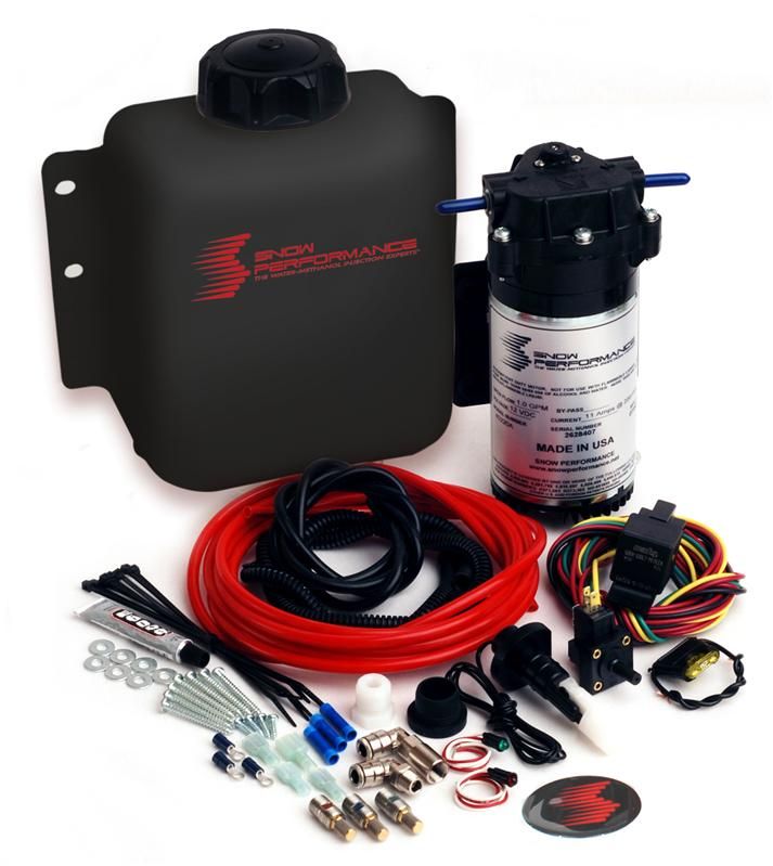 Snow Performance Stage 1 Water Methanol Injection Kit Sno 201 40040 Snosno 40040 Universal Concept Z Performance
Https Www Rpmoutlet Com Pdf Snow20100 Pdf


